Home

Calligrafia ingegneri energia compressor pv diagram Cavalcata Offerta di lavoro Influenzare

6: p-v diagram for reciprocating and screw compressor. | Download  Scientific Diagram
6: p-v diagram for reciprocating and screw compressor. | Download Scientific Diagram

Vapor-Compression Refrigeration | Refrigerator, Vapor, Compression

Applied Thermodynamics Module 6: Reciprocating Compressor

The actual PV diagram of reciprocating compressor | Download Scientific  Diagram
The actual PV diagram of reciprocating compressor | Download Scientific Diagram

Detecting cracks in reciprocating compressor valves using pattern  recognition in the pV diagram | Pattern Analysis and Applications
Detecting cracks in reciprocating compressor valves using pattern recognition in the pV diagram | Pattern Analysis and Applications

2 Reciprocating Air Compressors (Working and p-v diagram) - YouTube

Compressors – Working and Characteristics

Reciprocating Compressor Basics

Air Compressor Operation: Description of Two Stage and Theory

Part2] Reciprocating compression of air – Thermodynamics on PV and TS  diagram
Part2] Reciprocating compression of air – Thermodynamics on PV and TS diagram

Two Stage Compressor | How does a 2 Stage Air Compressor work?

Why is major part of the work in compressing the air done by LP cylinder of  a two-stage air compressor? Why isn't an equal amount of work done in each  stage? -
Why is major part of the work in compressing the air done by LP cylinder of a two-stage air compressor? Why isn't an equal amount of work done in each stage? -
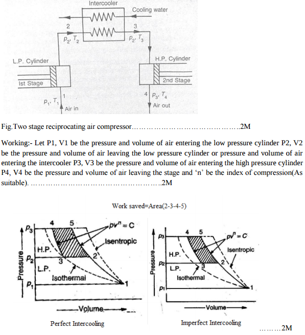
Explain the working of two stage reciprocating compressor....... |  Mechanical Engg Simple Notes ,Solved problems and Videos
Explain the working of two stage reciprocating compressor....... | Mechanical Engg Simple Notes ,Solved problems and Videos

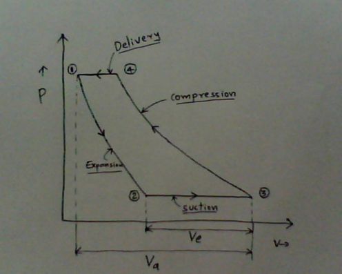
P-V Indicator Diagram with solved Examples

UC or OC of a PD compressor on P-V diagram, Huang [5] | Download Scientific  Diagram
UC or OC of a PD compressor on P-V diagram, Huang [5] | Download Scientific Diagram

Real or actual indicated diagram (p-v) for reciprocating compressor||part-4||unit-4||TEGD  - YouTube
Real or actual indicated diagram (p-v) for reciprocating compressor||part-4||unit-4||TEGD - YouTube

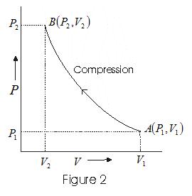
p - V diagram for an ideal reciprocating device. As shown the device is...  | Download Scientific Diagram
p - V diagram for an ideal reciprocating device. As shown the device is... | Download Scientific Diagram

Solved] The pressure-volume diagram of an ideal reciprocating air co

Solved] An ideal air compressor cycle (with clearance) on p-v diagra

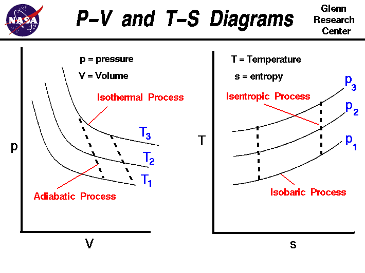
P-V and T-S Diagrams

File:PV and TS diagram compressor.JPG - Wikimedia Commons

Part2] Reciprocating compression of air – Thermodynamics on PV and TS  diagram
Part2] Reciprocating compression of air – Thermodynamics on PV and TS diagram

Work Done By Reciprocating Compressor without Clearance Volume (Single  Stage, Single Acting) With PV and TS Diagram
Work Done By Reciprocating Compressor without Clearance Volume (Single Stage, Single Acting) With PV and TS Diagram
The compressor indicator diagram - YouTube

Ch8, Lesson C, Page 14 - 3-Stage Compression With Intercooling

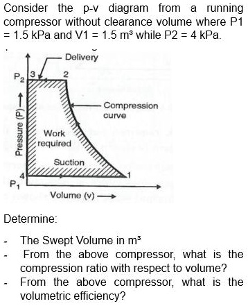
SOLVED: Title: Please Provide Answer and Solution Consider the p-v diagram  from a running compressor without clearance volume where P1 = 1.5 kPa and  V1 = 1.5 m while P2 = 4
SOLVED: Title: Please Provide Answer and Solution Consider the p-v diagram from a running compressor without clearance volume where P1 = 1.5 kPa and V1 = 1.5 m while P2 = 4